The first step in testing capacitors is a visual inspection. A run capacitor that is malformed or bulged in one area, especially at the top, normally indicates some type of defect. Start capacitors typically have a membrane on top which will blow open when they overheat.
Capacitors can fail open, shorted, and on rare occasions weak (its microfarad value being less than its rated value). The best method of testing capacitors is with a capacitance meter. This meter will identify all three problems. Many multifunctional meters sold today will include this feature. When purchasing a new meter, make sure it has this useful function.
ANALOG OHMMETER
If a technician does not have a capacitance meter, an analog ohmmeter can be used. However, this meter will only show if the capacitor is open or shorted.Below is a typical procedure used to test capacitors using an analog meter:
• Remove the capacitor from the circuit.
• Discharge capacitor with a bleed resistor or voltmeter.
• Set an ohmmeter to its lowest scale.
• Touch the probe ends together and zero the ohmmeter.
• Place the ohmmeter leads on the capacitor terminals.
• Watch for one of the following indications for the capacitor:
Good:Needle will swing toward zero and then slowly return to infinity;
Shorted:Needle will swing toward zero and remain there;
Open:Needle will stay at infinity.
• Make a second test by reversing the leads of the ohmmeter.
• If your meter indicates the capacitor is either shorted or open, retest the capacitor on a higher ohm’s scale to confirm your findings.
Run capacitors can also be tested for being grounded. Place one of the ohmmeter leads on a terminal of the capacitor and one lead on the body. If the ohmmeter reads a resistance, the capacitor is grounded and needs to be replaced. Be sure to test both terminals of the capacitor.
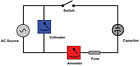
Figure 1. Sample circuit that can be configured to measure applied voltage and current draw of a capacitor.
ANOTHER METHOD
There is a method of measuring the capacitance value of a capacitor without the use of a capacitance meter. Once a technician has verified the capacitor is not opened or shorted, he can determine its capacitance by measuring its applied voltage and current draw. Once these values are known, the following formula can be used to determine its capacitance:Capacitance (µf) = (Measured Amperage x 2,650) ÷ Measured Voltage
Figure 1 is a sample circuit which can be configured to measure the applied voltage and current draw of a capacitor. Before applying any voltage to a capacitor, always test it for any shorts.
If the capacitor is shorted, do not proceed with the test. Do not apply a voltage higher than the rating of the capacitor - if unknown, use 110 volts. Do not apply voltage to a start capacitor for more than three seconds. Also place the start capacitor in a containment box before energizing. In the event of a failure, a start capacitor can overheat and expel flaming material. When testing run capacitors, only apply voltage long enough to obtain required readings.
Publication date:10/04/2010


Report Abusive Comment