
Figure 1: The primary purpose of the distributor and nozzle is to ensure each circuit on a multicircuited evaporator coil receives an equal amount of saturated (liquid and vapor) refrigerant.
Depending on the size of the equipment, this same component can cost hundreds, if not thousands, of dollars in labor trying to troubleshoot the system or because of lost efficiency over the life of the refrigeration equipment. Such is the case with the often overlooked or forgotten nozzle found in the refrigerant distributor.
This topic is increasingly relevant as more and more supermarket chains - concerned about the future availability and cost of HCFC-22 - convert their R-22 systems to more environmentally friendly and efficient refrigerants. As the pace of refrigerant conversions increase, more contractors, unfamiliar with how to properly perform a refrigerant conversion, will find themselves getting involved.
Following is a brief discussion regarding the purpose of the distributor nozzle, and how critical proper nozzle sizing during a refrigerant conversion is to maintaining system overall performance and efficiency.
PURPOSE
The primary purpose of the distributor and nozzle is to ensure each circuit on a multicircuited evaporator coil receives an equal amount of saturated (liquid and vapor) refrigerant. This equal distribution is accomplished by directing the saturated refrigerant exiting the TXV and sending it through the orifice of the nozzle.The reduced area of the orifice causes the refrigerant to accelerate and directs the refrigerant towards the tip of the dispersion cone. This refrigerant traveling at a high velocity hits the dispersion cone creating a homogeneous mixture of liquid and vapor. This homogenous mixture then travels down the circuit tubes with an equal amount of refrigerant being delivered to each evaporator circuit, thus ensuring the maximum amount of heat transfer is achieved and peak coil efficiency (Fig. 1).

Figure 2: If all the temperatures are within a few degrees of each other, then you have good refrigerant distribution.
ORIFICE IS TOO LARGE
If the nozzle’s orifice is too large, the refrigerant will not have enough velocity to create a homogeneous mixture, and the liquid and vapor will separate. Since liquid refrigerant is denser, it will settle to the bottom, causing the circuits connected to the lower portion of the distributor to receive more liquid, while the upper circuits are fed more vapor. This creates unequal circuit loading which decreases the capacity of the evaporator and/or causes the TXV to hunt.Why will it hunt? The TXV senses the bottom circuit flooded with liquid refrigerant, 0°F of superheat, and forces the TXV to close. This causes the top circuits already starved of refrigerant to operate at an even higher superheat. Once the bottom circuit is no longer flooding through with liquid, the TXV will sense the high superheat from the upper circuits and will want to quickly open, only to once again flood the bottom circuit and start the cycle all over again. Mounting the distributor in a vertical position may help, but is not the cure for all systems with an oversized orifice.
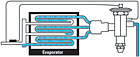
Figure 3: If the temperatures are more than a few degrees apart, then you may have poor refrigerant distribution.
If all the temperatures are within a few degrees of each other, then you have good refrigerant distribution (Fig. 2).
If the temperatures are more than a few degrees apart, then you may have poor refrigerant distribution (Fig. 3). Uneven airflow or an unevenly distributed heat load across the coil can produce the same results. This only applies to refrigeration coils, not air conditioning A or N coils.
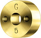
Figure 4: When doing your first walk through to determine what parts will be needed to complete the conversion, write down all the evaporator model numbers on all walk-in coolers and freezers, along with the distributor model types. You will need this information to properly size the nozzles and their orifices.
ORIFICE IS TOO SMALL
A nozzle with an undersized orifice also has the potential to cause problems. If the orifice is too small, excessive pressure drop across the distributor nozzle is produced. Keep in mind that pressure drop is one of the major factors in determining TXV capacity. Any excessive pressure drop created by the undersized orifice will rob the TXV of its available pressure drop, and will reduce the capacity of the TXV.This reduction in TXV capacity may cause excessive pull down times at startup, after a defrost cycle, or may not allow the system to pull down to its operating temperature. To counteract this reduction in capacity, some contractors will simply lower the suction pressure settings so the system can reach temperature.
Lowering the suction pressure will cause the system to operate less efficiently and potentially negate any gains obtained by moving to the more efficient refrigerants. (Table 1 shows the recommended pressure drops across the distributor nozzle and circuit tubes). Don’t be alarmed if there isn’t 10-pounds per square inch drop through the circuit tubes. Circuit tubes are provided with the coils that have been tested and approved for use by the coil manufacturers. If this is the case, then size the nozzle’s orifice accordingly to achieve the total recommended pressure drop. There are many tools to help calculate the pressure drop across the nozzle and circuit tubes, such as the Sporlan Selection and Sizing Program, which can be obtained free of charge.
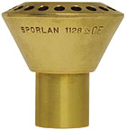
Figure 5: The distributor model type is needed to determine the nozzle size or letter, and the evaporator model number will be used to determine the orifice size or number.
CONVERSIONS
Now that we’ve discussed the potential problems with incorrectly sized nozzle orifices, let’s discuss some things you should keep in mind when performing a refrigerant conversion.First, an orifice’s capacity will change as you change from one refrigerant to another. For example, the same size orifice that feeds 0.96 tons of capacity for R-22 will only feed 0.63 tons for HFC-404A, or 0.56 tons for HFC-422D on a 20° evaporator. As you can see, the capacity of the nozzle’s orifice is greatly affected when switching to or from R-22. Be very careful when working with those so-called drop-in refrigerants for R-22. The TXV and nozzle capacities will be reduced.
You are probably thinking no customer will pay for you to check and/or replace all the nozzles in all of their display cases. Don’t worry. Most case manufacturers have standardized their coils to help keep down costs. Since a manufacturer will use the same coil for a wide range of refrigerants, they have selected a nozzle that will provide proper performance no matter the refrigerant. However, checking the sizing of the nozzles’ orifices on all walk-in coolers and freezers is crucial.
Second, when doing your first walk-through to determine what parts will be needed to complete the conversion, write down all the evaporator model numbers on all walk-in coolers and freezers, along with the distributor model types. You will need this information to properly size the nozzles and their orifices (Fig. 4).
The distributor model type is needed to determine the nozzle size or letter, and the evaporator model number will be used to determine the orifice size or number (Fig. 5).

Table 1: *For systems that regularly operate between 50 and 100 percent of full load capacity, it is common to select a nozzle and tubes that have a combined pressure drop of 10-psi greater than this table. This a good practice. The only precaution is to verify this thermostatic expansion valve capacity at the reduced pressure drop across its port.
Finally, some customers will add a mechanical subcooler to their system to help improve system efficiency and/or to help counteract the reduction in TXV capacity when switching from R-22. This increase in capacity also applies to the nozzle. A decrease in liquid temperature from 100° to 50° will double the capacity of the nozzle. Again, make sure to check TXV and nozzle sizing if adding or removing a mechanical subcooler.
THE FORGOTTEN COMPONENT
To reiterate, the distributor nozzle is often the most forgotten component in a system. It’s such a simple device that most people will overlook it, or downplay its importance. But to the contractor who has replaced several TXVs trying to fix a hunting TXV, or to a storeowner who has to pay extra in utility bills every month, it is very important.Publication date:10/06/2008

Report Abusive Comment