There’s a lot of money on the table in operating costs for these systems. More than 40 percent of the energy consumed in most manufacturing plants is used to power fans, pumps, and ventilators. In some cases, the annual operating costs of a system may actually exceed the initial capital cost within two years of installation. Opportunities for improvement reside in the air power equation.
Power required for an air-handling system is computed with the following factors:
• Volumetric flow rate “Q,” stated in ft3/min (cubic feet per minute);
• Total pressure (resistance due to friction in ducts, hoods, and ΔP [pressure drop] of control device, etc.) “TP” stated in inches of water (inches-H20);
• Density factor of the gas being collected “df” (dimensionless): and
• Efficiency of the fan, “η” (dimensionless).
(Note: Dimensionless means it is a number without a description such as “miles per hour” or “feet,” etc. Fan efficiency is stated as a percent of 100, so a fan operating at 65 percent efficiency would have a value of 0.65 in the equation. Similarly, df [density factor] is defined as the density of the gas compared to Standard Air [defined as moistureless air at sea level and 70°F]. So, density units divided by density units cancel, and the number has no dimension. Air at 600° has a density of 0.0375 pounds per cubic foot. Air at Standard conditions has a density of 0.075 pounds per cubic foot. So, the density factor for 600° air is [0.0375 / 0.075 = ] 0.50.
The number 6,356 is a constant, and it converts the values in the equation into horsepower [hp].)

Small reductions in the numerator can have a significant cost impact. For example, a typical 20,000-cfm baghouse requires 60 or more hp for operation. A reduction of 1,000 cfm with improved hood design, or reduction of 1 inch static pressure with an improved duct or baghouse system, can save as much as $4,000 per year.
There are always limits on what can be done, however. The process may require a certain airflow or hooding arrangement, and that will dictate air volume. Adjustments to system pressure and fan efficiency may be better places to effect reductions.
System pressure is usually affected by two factors:
1.Hood and duct resistance as a function of velocities in the system and the inefficiencies of flow (poorly designed hoods, short-radius elbows, branch entry angles greater than 45 degrees, abrupt contractions, and elbows and other interferences at fan inlets and outlets - called fan system effects, etc.).
2.Resistance across the emission control device. A baghouse that operates at a pressure drop of 8 inches H2O will require twice the power of a collector operating at 4 inches H2O. However, the lower pressure drop collector may not provide the capture efficiency of the baghouse with higher pressure drop.
Of course, you can lower the pressure drop in a baghouse by adding filter area, but this means a larger housing. More important, baghouses often perform best at high pressure drops. The key is to minimize pressure drop while still meeting emission requirements. Excess static pressure just wastes power.

FIGURE 1. According to Gerry Lanham, a side draft hood
located twice the distance from the source can require as much as four times
the exhaust volumetric flow rate as a total enclosure.
HELPFUL TIPS
Here are some tips to help find that narrow range of safe and efficient operation.1. Minimize flow:Systems directly connected to a process source are inherently volume-limited, whereas systems that capture emissions with enclosures or hoods need to be optimized during the design process. Total enclosure of an emission source minimizes airflow and worker exposure. However, such enclosures can restrict visual observation of the process and hinder maintenance access.
Hoods that cannot be designed for total enclosure should be located as close to the source as possible. A side draft hood (see Figure 1) located twice the distance from the source can require as much as four times the exhaust volumetric flow rate as a total enclosure.
Capture hoods for high-velocity emissions (from grinding, sawing, etc.) must be located so the opening is in the direct path of the dust, fume, or mist. The American Conference of Governmental Industrial Hygienists publication “Industrial Ventilation - A Manual of Recommended Practice” provides guidelines for good design of hoods, duct, and similar equipment.
Other factors such as explosive limits for the gas being collected, moisture content (dew point), and heat content may influence the air volumetric flow rate requirements so there may be limits to the optimization.
2. Minimize pressure:Pressure offers greater opportunities to reduce energy costs. A system with good airflow characteristics (duct velocities and sizes optimized), matched with the proper control device, pressure monitors, and variable-frequency drives, can help manage system pressure. Most bag houses or other collection devices will have varying pressure drops over the life of the system. Bags are generally more efficient at higher pressure drop, but then use more energy. Scrubbers, oxidizers, and electrostatic precipitators tend to operate at more constant resistance.
A good pressure monitoring system that controls system volumetric flow rate can save thousands of dollars every year on the operation of even medium-sized systems. As variable-frequency drives become less expensive, they are now being found on many installations, especially systems of over 10,000 cfm.
Be mindful of duct inefficiencies and fan system effects (elbows at inlets and outlets, etc.). These shortcuts increase static pressure and operating costs for the life of the system. Short-radius elbows and systems can add thousands of dollars per year in wasted power.
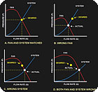
FIGURE 2. According to Gerry Lanham’s calculations, any of
the three improper fan/system matches wastes power and produces unsatisfactory
system performance.
4. Fan efficiency:The design of the fan and its blade type can greatly affect efficiency and power requirements. Laboratory-measured peak fan efficiency may not be the most stable point of operation. If peak efficiency coincides with the peak of the pressure curve, then there may be operational problems as volumetric flow rates vary with small changes in system pressure. The designer must consider both curves when selecting the best fan and operating point to optimize reliability and power usage.
And fan type may dictate proper selection. Airfoil wheels, while more efficient, may not be a good choice when handling particulate-laden air.
The key to any design is proper fan selection. (Figure 2 illustrates the importance of matching the fan to the system, as calculated.) Any of the three improper matches waste power and produce unsatisfactory system performance.
SUMMARY
The power equation identifies four main areas - volumetric flow rate, pressure, density, and fan efficiency - that affect energy consumption. The challenge for industry is to operate in the narrow functional range that guarantees system effectiveness with minimum energy consumption. Attention to the air power equation can help meet those goals.Sidebar: In Addition to Energy...
According to Gerry Lanham, president of KBD/Technic, here are some good design goals for any team studying new projects or system alterations.1.Protect worker and public health by meeting local/national standards for in-plant air and exhaust.
2.Provide an efficient connection to the process through proper hood design or direct connection to the process, while considering safety for fire, explosion, and process reactions, as well as the ergonomics of process access.
3.Minimize auxiliary costs (compressed air, natural gas, water, etc.).
4.Minimize replacement costs (filter bags, neutralizing chemicals, etc.).
5.Provide an easily maintained and accessible system.
6.Make the system simple to operate and train personnel to ensure ongoing performance.
7.Look for opportunities to recycle tempered air back to the plant or process by filtering exhaust through redundant systems.
Publication date:06/18/2007

Report Abusive Comment