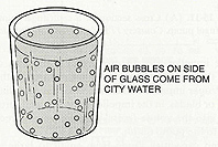
Figure 1. This standing glass of water from
the city water supply shows there is air in water. All you have to do is fill a
glass and watch what happens after it stands for a while. (From Practical Heating Technology,
by William Johnson, published by Thomson Delmar Learning.)
Bob asked, “What do you think the cause could be?”
Btu Buddy said, “Two things come to mind. If the system has a leak, where water is being lost, the makeup water could cause air to build up in the system. City water is used as the makeup water and it contains air. You probably have noticed that if you leave a glass of water out on the table that air bubbles appear in it (Figure 1). If enough city water is allowed into the system from leaks, air will accumulate at the high point in the system. Another possible cause is that the hot water pump is sucking in air around the pump shaft seal (Figure 2). We should do some checking around for leaks and test the pump inlet and see if it is running in a vacuum.”
Bob asked, “How are we going to check the system for water leaks?”
Btu Buddy said, “If there are water leaks at the individual units, water will be dripping from the condensate drain lines. Notice that all of the units are on an outside wall and you can see the drain lines coming out the wall and they drip outside into the flowers or on the ground. Let’s walk around the motel and see if any are dripping.”
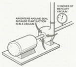
Figure 2. This pump seal is running in a
vacuum. If the seal leaks while it is running, air will be sucked in. (From Practical Heating Technology,
by William Johnson, published by Thomson Delmar Learning.) (Click on the image for an enlarged view.)
Bob said, “I wonder how long those have been leaking?”
Btu Buddy responded, “Probably a long time. For every bit of water that leaks out, water must be made back up with city water. As we talked about earlier, city water has air in it. I think that we have solved the leak problems from the fan coil units. Let’s go to the boiler room and see if we find any leaks there.”
They went to the boiler room and found a leak at a valve packing on one of the pipes. The valve packing gland was tightened and the leak stopped (Figure 3).
Bob then said, “I think that we have all of the obvious leaks repaired. It is likely that if there were more they would show because they would be in the piping in the walls and ceilings.”
Btu Buddy then said, “Let’s put some gauges on the pump and see what it says.”
Bob put some water gauges on the inlet and the outlet to the pump and said, “The inlet is in a vacuum and the outlet is reading 50 psig. You were right, the vacuum would pull in air if the seal leaks.”
Btu Buddy said, “Notice that there is a valve at the pump inlet and the outlet. The inlet valve is partially closed. Someone has tried to limit the flow across the pump. Let’s get an ammeter and see what the amperage is.”

Figure 3. The packing gland can be tightened
to prevent it from leaking. (From Practical
Heating Technology, by William Johnson, published by Thomson
Delmar Learning.) (Click on the image for an enlarged view.)
Btu Buddy said, “Watch the ammeter when you open the suction valve to the pump.”
Bob began to open the valve and the amperage began to rise above full load.
Btu Buddy said, “Now close the outlet valve and bring the amperage down.”
Bob asked, “Won’t the amperage rise if I start to close the pump discharge?”
Btu Buddy explained, “It doesn’t matter how you reduce the flow across a centrifugal pump, you can either use the inlet or the discharge. When you reduce the water flow, the amperage will reduce (Figure 4). It would be different if it were a positive displacement pump; you could not shut down the outlet without causing the amperage to rise.”
Bob asked, “How would I know the difference?”

Figure 4. This illustration shows that
throttling a centrifugal pump at the pump outlet causes the amperage to go
down. You would think that increasing the outlet pressure would cause the
amperage to rise, but it is actually flow through the pump that causes
electrical current rise. More flow, more amperage. (From Refrigeration
& Air Conditioning Technology, 5th Edition, by William
Whitman, William Johnson, and John Tomczyk, published by Thomson Delmar
Learning.) (Click on the image for an enlarged view.)
Bob began to close down the outlet valve and the amperage dropped back to full load amps.
Btu Buddy said, “Now see if you can control the pump to full load amps by opening the inlet valve all the way and closing down on the outlet valve.”
Bob kept experimenting until the inlet was wide open and the outlet was partially closed.
Btu Buddy said, “You now have the same water flow. What is the inlet pressure?”
Bob looked and said, “We now have 10 psig of inlet pressure and 55 psig of outlet pressure. If the pump running in a vacuum was causing a leak, it won’t now.”
Bob asked, “Why did someone throttle the pump inlet in the first place?”
Btu Buddy explained, “The technician that throttled the pump inlet just did not know the facts.”
As they were closing down the job, Bob said, “Thanks for filling me in on how this is working. There is a lot to this job. I bet I never forget this one.”
Part 1, “Btu Buddy 46: Air in a Hot Water Heating System,” appeared in the Jan. 22, 2007 issue of Extra Edition.
Publication date:02/19/2007


Report Abusive Comment