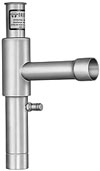
Figure 1: ‘Hold back’ valve at the outlet of the condenser.
The solution to the low head pressure problem is to install a pressure actuated “hold back” valve at the outlet of the condenser (Figures 1 and 2). This valve will throttle shut when the condenser pressure reaches a preset minimum for low ambient conditions. This will allow liquid refrigerant in the condenser to be held back and actually flood portions of the condenser.
This partial flooding will cause some of the condenser to become inactive and to have a smaller internal volume.
Now desuperheating and condensation must take place in a smaller volume condenser. Condensing pressures will rise, thus giving sufficient liquid line pressures and pressure differences across the thermostatic expansion valve (TXV) for normal system operation in the colder ambient.
The valve (Figure 3) is referred to as an ORI (Open on Rise of Inlet) valve. It is an inlet pressure-regulating valve and responds to changes to inlet pressure (condensing pressure) only. A decrease in condensing pressure causes less pressure to act on the bottom of the seat disc. This action throttles the valve more in the closed position and starts to back up liquid refrigerant in the bottom of the condenser.
Soon the head pressure will start to rise from the reduced condenser internal volume. Any increase in inlet (condensing pressure) above the valve setting will tend to open the valve. The condensing pressure is opposed by adjustable spring force acting on top of the seat disc.

Figure 2: Schematic showing positions of head pressure
control valves.
This is because the outlet pressure is exerted on top of the bellows and on top of the seat disc simultaneously. Since the effective area of the bellows is equal to the area of the top of the seat disc, the pressures cancel one another and do not affect the valve movement (Figure 3). Only changes in condensing pressure can throttle the valve either opened or closed.
An ORI valve is usually used in conjunction with the ORD (Open on Rise of Differential) valve (Figures 4 and 5). The ORD valve is located between the discharge line and the receiver inlet (Figure 2). It responds to changes in pressure differences across the valve. The ORD valve is thus dependent on the ORI valve for its operation. The ORD valve will bypass hot compressor discharge gas from the compressor to the receiver inlet when it senses a preset determined pressure difference across the valve.

Figure 3: Cutaway of ORI valve.
Once the ORI valve starts to throttle shut, the receiver is still supplying refrigerant to the TXV and its pressure will eventually drop. If the receiver pressure drops too low, its ability to keep feeding the liquid line and TXV’s liquid will diminish. Something has to keep receiver pressure up while the ORI valve is throttling liquid from the condenser. This is when the function of the ORD valve comes into play.
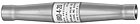
Figure 4: ORD valve.

Figure 5: An ORI valve is usually used in conjunction with
the ORD valve.
Publication date:05/07/2007


Report Abusive Comment