While misalignment has no measurable effect on motor efficiency, correct shaft alignment ensures the smooth, efficient transmission of power from the motor to the driven equipment. Incorrect alignment occurs when the centerlines of the motor and the driven equipment shafts are not in line with each other. Misalignment produces excessive vibration, noise, coupling and bearing temperature increases, and premature bearing or coupling failure.
TYPES OF MISALIGNMENT
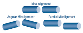
There are three types of motor misalignment:Angular misalignmentoccurs when the motor is set at an angle to the driven equipment. The angle or mismatch can be to the left or the right, or above or below. If the centerlines of the motor and the driven equipment shafts were to be extended, they would cross each other, rather than superimpose or run along a common centerline. Angular misalignment can cause severe damage to the driven equipment and the motor.
Parallel misalignmentoccurs when the two shaft centerlines are parallel, but not in the same line. They are offset horizontally or vertically (or both), displaced to the left or right, or positioned at different elevations.
Combination misalignmentoccurs when the motor shaft suffers from angular misalignment in addition to parallel misalignment.
COUPLINGS
Larger motors are usually directly coupled to their loads with rigid or flexible couplings. Rigid couplings do not compensate for any motor-to-driven-equipment misalignment while flexible couplings tolerate small amounts of misalignment. Flexible couplings can also reduce vibration transmitted from one piece of equipment to another, and some can insulate the driven equipment shaft against stray electrical currents. Even flexible couplings require a minimal alignment, defined in the instruction sheet for the coupling.It is a mistake, however, to take advantage of coupling flexibility for excessive misalignment, as flexing of the coupling and of the shaft will impose forces on the motor and driven-equipment bearings. Effects of these forces include premature bearing, seal, or coupling failures, shaft breaking or cracking, and excessive radial and axial vibrations. Secondary effects include loosening of foundation bolts, and loose or broken coupling bolts. Operating life is shortened whenever shafts are misaligned.
ALIGNMENT TOLERANCES
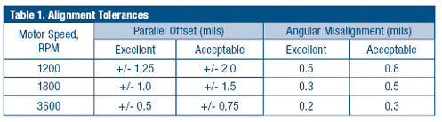
Proper shaft alignment is especially critical when the motor is operated at high speeds. Typical alignment tolerances are summarized in Table 1.In practice, proper alignment is difficult to achieve without using alignment equipment such as dial indicators or laser alignment tools to check and correct for misalignment. The proper shaft alignment procedure is to secure the driven equipment first, and then install the coupling to the equipment. Moving a pump, for instance, would impose stress upon the connecting piping. Then the motor should be moved into proper alignment and joined to the coupling.
After the equipment has operated long enough to become temperature stabilized, shut it down and immediately recheck alignment. Due to thermal growth, machines that are aligned in the “cold” pre-operating condition are almost always out of alignment when operating temperatures are attained. Many equipment manufacturers publish thermal offset values so the alignment professional can correct for thermal growth during the initial alignment process.
Suggested Actions
• Check shaft alignment of all critical equipment annually.• Monitor vibration as an indication of misalignment. Misalignment might be caused by foundation settling, insufficient bolt tightening, or coupling faults.
• After three to six months of operation, recheck newly installed equipment for alignment changes due to foundation settling.
• Predictive maintenance techniques, including vibration tests and frequency spectrum analysis, can be used to distinguish between bearing wear, shaft misalignment, or electrically caused vibrations.
Resources
Institute of Electrical Motor Diagnostics (IEMD)- For information on electrical motor diagnostic technologies and motor-system health, visit www.iemd.org.Electrical Apparatus Service Association (EASA)- Provides information on motor maintenance topics (www.easa.org).
U.S. Department of Energy (DOE)- For additional information on energy efficiency measures and training, visit the BestPractices Website at www.eere.energy.gov/industry/bestpractices.
Reprinted from Motor Systems Tip Sheet #4, “The Importance of Motor Shaft Alignment,” from the U.S. Department of Energy’s Office of Energy Efficiency and Renewable Energy. For more information, visit www.eere.energy.gov.
Publication date:05/07/2007

Report Abusive Comment