In heat reclaim when using the Type B three-way valve that has a bleed orifice, there may be rare occasions where the pilot connection to the suction header is frosted. Liquid refrigerant experiencing a reduction in pressure through the small pilot port will flash, producing a refrigeration effect. If the saturated suction temperature (or corresponding pressure) is at or below 32°F, the flashing will result in the pilot line frosting. One’s first inclination would be to suggest that this is the result of the refrigerant in the idle heat reclaim coil pumping out through the orifice in the main valve piston.
When using the Type B three-way valve, the refrigerant flowing through the main piston orifice during pump-out is coming from what would be the inlet of the heat reclaim coil. In the series method, the heat reclaim coil’s function is to desuperheat the discharge vapor only. As such, there should not be any liquid present in this coil.
Even if some small amount of liquid refrigerant were present during pump-out, the free draining nature of the heat reclaim coil (inlet at top, outlet at bottom) would prevent it from accumulating near the point of pump-out (the inlet). Therefore, if any liquid refrigerant is present during pump-out, gravity will force it to accumulate at the bottom of the heat reclaim coil, away from the point of pump-out.
Normal operation of the series heat reclaim application during pump-out will not allow for any liquid refrigerant at the point of pump-out. Only vapor should be present at the point of pump-out. Expanding a high-pressure vapor to a low-pressure vapor does not produce a refrigeration effect. Therefore, a normal operating series heat reclaim system should never have frost on the pilot connection to the suction header.
So what is the answer? Frosting of the pilot line can only happen if the heat reclaim coil is nearly full of liquid refrigerant during pump-out. There is a check valve at the outlet of the heat reclaim coil to retard refrigerant backflow into the heat reclaim coil during the condensing mode.
If the check valve developed substantial seat leakage, it would provide the reclaim coil with an unlimited source of refrigerant vapor that could completely fill the heat reclaim coil with liquid refrigerant over time. Because the air-handling fan is normally on, air at approximately 75° will be flowing through the heat reclaim coil’s tube bundle. This will cause the superheated discharge vapor leaking into the heat reclaim coil to condense, and experience a drop in pressure.
This then makes room for additional vapor to enter the heat reclaim coil, which too will condense and experience a drop in pressure, making room for additional vapor to enter the heat reclaim coil, which too will condense and experience a drop in pressure, until it is nearly completely full of liquid refrigerant.
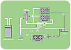
FIGURE 1.
SERIES METHOD CONSIDERATIONS
There is another potential problem when using the series heat reclaim method. Many refrigeration systems use condenser-flooding valves to maintain a minimum head pressure during low ambient conditions. An open on rise of inlet pressure valve (ORI) or A8 inlet pressure regulator (holdback valve) at the condenser outlet maintains a constant condensing pressure.A second valve (receiver pressurization valve) is located between the discharge line and the receiver, and maintains a constant receiver pressure. This can either be an A9 outlet pressure regulator, which maintains a constant receiver pressure based upon its set point, or an open on rise of differential (ORD) pressure valve, which maintains a constant differential between the discharge pressure and receiver pressure. A tee in the main discharge line will supply discharge vapor to the receiver pressurization valve (see Figure 1).
There is a natural pressure drop that exists between the outlet side of that tee and the inlet of the holdback valve; a combination of pressure drop in the piping and components (oil separator, ball valves, three-way valve, ORI/A8 valve, etc.), and pressure drop in the condenser.
The A9 valve’s set point (re-ceiver pressure) is independent of the setting of the holdback valve, or the accumulated pressure drop between the outlet of the tee and the inlet of the holdback valve. The ORD’s function in maintaining receiver pressure is very dependent on this pressure drop and the holdback valve’s set point.
For example: The ORI/A8 valve is set to maintain a 185-psi pressure at its inlet. Receiver pressurization is achieved with an ORD-4-20 check valve. It begins to open at a 20-psi differential, and flows its rated capacity at a 30-psi differential. It begins to close at a 14-psi differential.
If the pressure drop between the outlet of the tee and the inlet of the holdback valve during the normal condensing mode were 5 psi, then the pressure at the ORD inlet would be 190 psi (ORI/A8 setting plus the 5-psi pressure drop). The receiver pressure would be at 170 psi (190-psi discharge pressure minus the 20-psi differential at which the ORD opens).
The series method of heat reclaim offers the greatest potential for total pressure drop between the discharge line and the inlet of the holdback valve. It includes the combined total pressure drop from the reclaim coil and the normal condenser, plus the associated piping and components for both. In an application with long piping runs between the heat reclaim coil and the condenser, the possibility exists where the total pressure drop could exceed the point at which the ORD-4-20 differential check valve begins to close. In extreme cases, the total pressure drop might exceed the point at which the valve would start to open, causing it to remain open indefinitely.
For example: The holdback valve is again set for 185 psi, and the pressure drop between the discharge line and the inlet of the holdback valve is 17 psi. The pressure at the ORD inlet would be 202 psi (ORI setting plus the 17-psi pressure drop), and the receiver pressure would be 182 psi (202-psi discharge less the 20-psi differential at which the ORD opens).
Because of the pressure drop, there will always be a minimum 17-psi differential between inlet and outlet of the ORD during the heat reclaim mode. As the need for head pressure control subsides, the holdback valve would cease holding back (wide-open operation) and the receiver pressurization valve would throttle closed.
However, with a 17-psi pressure drop, the minimum 14-psi differential at which the ORD-4-20 starts to close will never be realized. The differential check valve would continually bypass hot gas to eliminate the 3-psi difference between the available pressure drop (17 psi) and the point at which it starts to close (14 psi). This would only be a problem when operating conditions do not require the holdback valve to maintain a minimum condensing pressure, yet heat reclaim is required. This would be an infrequent condition when using heat reclaim to provide the building’s heat. Because of hot-water reclaim’s year-around demand, it would offer more potential for this circumstance to occur.
To realize the negative impact of this situation requires an understanding of the dynamic condition that exists within the receiver. It is true that in a static condition a vessel containing refrigerant will be at a saturated condition relative to the ambient temperature. In a dynamic condition such as an operating system, it is common for the entering refrigerant to be subcooled.
Given the fact that a receiver is a poor heat transfer device, where does the required heat gain come from to bring this refrigerant to a saturated condition? It doesn’t. In a dynamic system, there isn’t enough time for the required amount of heat to transfer through the receiver wall and heat the liquid to a saturated condition.
The point of interface between the liquid and vapor present in the receiver will be at a saturated condition. Below this point there will be a stratification of liquid, with the very bottom of the receiver containing the coolest liquid. The closer the liquid temperature is to the evaporating temperature, the more efficient it will be in transferring heat from the refrigerated space.
Unnecessarily adding hot gas to the receiver will increase the leaving liquid temperature, resulting is a less efficient use of the liquid. This will require an increase in refrigerant mass flow, resulting in lower equipment efficiency and higher operating costs.
If receiver pressurization is maintained with an ORD check valve, it should be selected with a rated closing point which is greater than the combined pressure drop between the discharge tee outlet and the receiver inlet. If an A9 outlet regulator is used for receiver pressurization, its normal operation will not be impacted by excessive pressure drop between the discharge line and the receiver inlet. As an outlet pressure regulator, its function is to provide a constant receiver pressure, and its ability to maintain this is not impacted by the pressure difference between its inlet and outlet.
HEAT RECLAIM: IS IT VIABLE?
There are some who suggest that using heat reclaim to provide a source for building heat is not a huge energy saver. The argument goes something like this: Higher condensing pressures are required to generate sufficient discharge temperatures from which heating can be achieved. While building heat reclaim will eliminate the need for the additional equipment and energy source necessary for heating, the required higher condensing pressures reduce compressor efficiency.In the winter, the energy saved from operating at low condensing temperatures will be greater than the gain from heating the store with heat reclaim at higher condensing temperatures. Perhaps there is some validity to this argument. However, it doesn’t hold true when applied to a hot-water heat reclaim application. While operating at the lowest possible ambient in the winter, there will still be some heat content that can be transferred from the discharge vapor to the water in a hot-water reclaim tank. Because hot water is in demand year-round, its benefit can be maximized during the warmer months.
Today’s climate of energy conservation demands that every effort be made to increase system efficiency. The compression process, while an essential component of the vapor-compression cycle, is nothing more than a means to an end. It is a necessary evil that requires the expenditure of energy to accomplish it.
Some of that energy is converted to heat, a waste byproduct. Heat reclaim takes advantage of this existing situation and extracts some benefit from it. Using heat reclaim to heat a building may not be the most efficient choice. However, there is demand for hot water year-round, and heat reclaim converts waste into a reduction in energy consumption.
Publication date:05/28/2007

Report Abusive Comment