
INTRODUCTION
Multimeters. They've been described as the tape measure of the new millennium. But what exactly is a digital multimeter (DMM) and what can you do with it? How do you make measurements safely? What features do you need? What is the easiest way to get the most out of your meter? Which meter is best suited to the environment you're working in? These and other questions are answered in this article.Technology is rapidly changing our world. Electrical and electronic circuitry seems to permeate everything, and continues to get more complex and smaller in size. Servicing, repairing, and installing this complex equipment requires diagnostic tools that provide accurate information.
Let's begin by explaining what a DMM is. A DMM is simply an electronic tape measure for making electrical measurements. It may have any number of special features, but mainly a DMM measures volts, ohms, and amperes.
This article explains common uses and tips for using most DMMs. It discusses how to use a DMM to make measurements, and how DMMs differ from one another.
SOME BASICS
Resolution, digits and countsResolution refers to how fine a measurement a meter can make. By knowing the resolution of a meter, you can determine if it is possible to see a small change in the measured signal. For example, if the DMM has a resolution of 1 mV on the 4 V range, it is possible to see a change of 1 mV (1/1,000 of a volt) while reading 1 V.
You wouldn't buy a ruler marked in one-inch (or one-centimeter) segments if you had to measure down to a quarter inch (or one millimeter). A thermometer that measures only in whole degrees isn't much use when your normal temperature is 98.6 degrees Fahrenheit. You need a thermometer with one-degree resolution.
The terms digits and counts are used to describe a meter's resolution. DMMs are grouped by the number of counts or digits they display.
A 3-1â„2-digit meter can display three full digits ranging from 0 to 9, and one "half" digit which displays only a 1 or is left blank. A 3-1â„2-digit meter will display up to 1,999 counts of resolution. A 4-1â„2-digit meter can display up to 19,999 counts of resolution.
It is more precise to describe a meter by counts of resolution than by digits. Today's 3-1â„2-digit meters may have enhanced resolution of up to 3,200, 4,000, or 6,000 counts.
For certain measurements, 3,200-count meters offer better resolution. For example, a 1,999-count meter won't be able to measure down to a tenth of a volt if you are measuring 200 volts or more. However, a 3,200-count meter will display a tenth of a volt up to 320 volts. This is the same resolution as a more expensive 20,000-count meter until you exceed 320 volts.
Accuracy
Accuracy is the largest allowable error that will occur under specific operating conditions. In other words, it is an indication of how close the DMM's displayed measurement is to the actual value of the signal being measured.
Accuracy for a DMM is usually expressed as a percent of reading. An accuracy of 1 percent of reading means that for a displayed reading of 100 volts, the actual value of the voltage could be anywhere between 99 volts and 101 volts.
Analog meter specifications are determined by the error at full scale, not at the displayed reading. Typical accuracy for an analog meter is ± 2 percent or ± 3 percent of full scale. At one-tenth of full scale, these become 20 percent or 30 percent of reading. Typical basic accuracy for a DMM is between ± (0.7 percent + 1) and ± (0.1 percent + 1) of reading, or better.
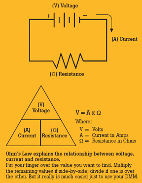
Ohm's law
Voltage, current, and resistance in any electrical circuit can be calculated by using Ohm's law, which states that voltage equals current times resistance (see Figure 1). Thus, if any two values in the formula are known, the third can be determined.
A DMM makes use of Ohm's law to directly measure and display either ohms, amps, or volts.
Digital and analog displays
For high accuracy and resolution, the digital display excels, displaying three or more digits for each measurement.
The analog needle display is less accurate and has lower effective resolution because you have to estimate values between the lines.
A bar graph shows changes and trends in a signal just like an analog needle, but is more durable and less prone to damage.
DC AND AC VOLTAGE
Measuring voltageOne of the most basic tasks of a DMM is measuring voltage. A typical DC voltage source is a battery, like the one used in your car. AC voltage is usually created by a generator. The wall outlets in a home are common sources of AC voltage. Some devices convert AC to DC. For
example, electronic equipment such as TVs, stereos, VCRs, and computers that you plug into an AC wall outlet use devices called rectifiers to convert the AC voltage to a DC voltage. This DC voltage is what powers the electronic circuits in these devices.
Testing for proper supply voltage is usually the first step when troubleshooting a circuit. If there is no voltage present, or if it is too high or too low, the voltage problem should be corrected before investigating further.

Most DMMs are "average responding," giving accurate rms readings if the AC voltage signal is a pure sine wave. Average responding meters are not capable of measuring non-sinusoidal signals accurately. Non-sinusoidal signals are accurately measured using DMMs designated "true-rms" up to the DMM's specified crest factor. Crest factor is the ratio of a signal's peak-to-rms value. It's 1.414 for a pure sine wave, but is often much higher for a rectifier current pulse, for example. As a result, an average responding meter will often read much lower than the actual rms value.
A DMM's ability to measure AC voltage can be limited by the frequency of the signal. Most DMMs can accurately measure AC voltages with frequencies from 50 Hz to 500 Hz, but a DMM's AC measurement bandwidth may be hundreds of kilohertz wide. Such a meter may read a higher value because it is "seeing" more of a complex AC signal. DMM accuracy specifications for AC voltage and AC current should state the frequency range along with the range's accuracy.
How to make voltage measurements
1. Select V (AC) or V (DC), as desired.
2. Plug the black test probe into the COM input jack. Plug the red test probe into the V input jack.
3. If the DMM has manual ranging only, select the highest range so as not to overload the input.
4. Touch the probe tips to the circuit across a load or power source (in parallel to the circuit).
5. View the reading, being sure to note the unit of measurement.
Note: 1/1,000 V = 1 mV and 1,000 V = 1 kV
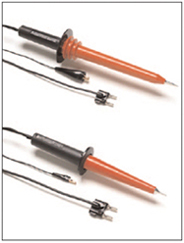
High-voltage probes are available for such applications as CRT repair, where voltages can reach 40 kV (see Figure 3).
Caution: These probes are not intended for electrical utility applications in which high voltage is also accompanied by high energy. Rather, they are intended for use in low-energy applications.
RESISTANCE, CONTINUITY AND DIODES
ResistanceResistance is measured in ohms (Ω). Resistance values can vary greatly, from a few milliohms(mΩ) for contact resistance to billions of ohms for insulators. Most DMMs measure down to 0.1 Ω, and some measure as high as 300 MΩ (300,000,000 ohms). Infinite resistance (open circuit) is read as "OL" on a Fluke meter display, and means the resistance is greater than the meter can measure.
Resistance measurements must be made with the circuit power off - otherwise, the meter or circuit could be damaged. Some DMMs provide protection in the ohms mode in case of accidental contact with voltages. The level of protection may vary greatly among different DMM models.
For accurate, low-resistance measurements, resistance in the test leads must be subtracted from the total resistance measured. Typical test lead resistance is between 0.2 Ω and 0.5 Ω. If the resistance in the test leads is greater than 1 Ω, the test leads should be replaced.

How to make resistance measurements:
1. Turn off power to the circuit.
2. Select resistance (Ω).
3. Plug the black test probe into the COM input jack. Plug the red test probe into the Ω input jack.
4. Connect the probe tips across the component or portion of the circuit for which you want to determine resistance.
5. View the reading, being sure to note the unit of measurement - ohms (Ω), kilohms (kΩ), or megohms (MΩ).
Note: 1,000 Ω = 1 kΩ and 1,000,000 Ω = 1 MΩ
Make sure the power is off before making resistance measurements.
Continuity
Continuity is a quick go/no-go resistance test that distinguishes between an open and a closed circuit.
A DMM with a continuity beeper allows you to complete many continuity tests easily and quickly. The meter beeps when it detects a closed circuit, so you don't have to look at the meter as you test. The level of resistance required to trigger the beeper varies from model to model of DMM.

A diode is like an electronic switch. It can be turned on if the voltage is over a certain level, generally about 0.6 V for a silicon diode, and it allows current to flow in one direction.
When checking the condition of a diode or transistor junction, an analog VOM not only gives widely varying readings but can drive currents up to 50 mA through the junction. (See Table 1).
Some DMMs have a diode test mode. This mode measures and displays the actual voltage drop across a junction. A silicon junction should have a voltage drop less than 0.7 V when applied in the forward direction and an open circuit when applied in the reverse direction.
DC AND AC CURRENT
Measuring currentCurrent measurements are different from other DMM measurements. Current measurements taken with the DMM alone require placing the meter in series with the circuit being measured. This means opening the circuit and using the DMM test leads to complete the circuit. This way all the circuit current flows through the DMM's circuitry. An indirect method of measuring current on a DMM can be performed using a current probe. The probe clamps around the outside of the conductor, thus avoiding opening the circuit and connecting the DMM in series.
How to make current measurements
1. Turn off power to the circuit.
2. Cut or unsolder the circuit, creating a place where the meter probes can be inserted.
3. Select A (AC) or A (DC) as desired.
4. Plug the black test probe into the COM input jack. Plug the red test probe into the amp or milliamp input jack, depending on the expected value of the reading.
5. Connect the probe tips to the circuit across the break so that all current will flow through the DMM (a series connection).
6. Turn the circuit power back on.
7. View the reading, being sure to note the unit of measurement.
Note: If the test leads are reversed for a DC measurement, a "–" will show in the display.
Input protection
A common mistake is to leave the test leads plugged into the current input jacks and then attempt a voltage measurement. This causes a direct short across the source voltage through a low-value resistor inside the DMM, called a current shunt. A high current flows through the DMM and, if it is not adequately protected, can cause extreme damage to both the DMM and the circuit, and possible injury to the operator. Extremely high fault currents can occur if industrial high-voltage circuits are involved (240 V or higher).
A DMM should therefore have current input fuse protection of high enough capacity for the circuit being measured. Meters without fuse protection in the current inputs should not be used on high-energy electrical circuits (> 240 V ac). Those DMMs that do use fuses should have a fuse with sufficient capacity to clear a high-energy fault. The voltage rating of the meter's fuses should be greater than the maximum voltage you expect to measure. For example, a 20 A, 250 V fuse may not be able to clear a fault inside the meter when the meter is across a 480 V circuit. A 20 A, 600 V fuse would be needed to clear the fault on a 480 V circuit.
Current probe accessories
Sometimes you may have to make a current measurement that exceeds the rating of your DMM or the situation does not allow you to open the circuit to measure the current. In these higher current applications (typically over 2 A), where high accuracy is not needed, a current probe is very useful. A current probe clamps around the conductor carrying the current, and it converts the measured value to a level the meter can handle.
There are two basic types of current probes: current transformers, which are used to measure AC current only, and Hall-Effect probes, which are used to measure AC or DC current.
The output of a current transformer is typically 1 milliamp per amp. A 100 amp value is reduced to 100 milliamps, which can be safely measured by most DMMs. The probe leads are connected to the "mA" and "COM" input jacks, and the meter function switch is set to mA AC.
The output of a Hall-Effect probe is 1 millivolt per amp, AC or DC. For example, 100 A AC is converted to 100 mV AC. The probe leads are connected to the "V" and "COM" jacks. Set the meter function switch to the "V" or "mV" scale, selecting V for AC current or V for DC current measurements. The meter displays 1 millivolt for every amp measured.
SAFETY
Multimeter safetyMaking measurements safely starts with choosing the proper meter for the application as well as the environment in which the meter will be used. Once the proper meter has been chosen, you should use it by following good measurement procedures. Carefully read the instrument user manual before use, paying particular attention to the WARNING and CAUTION sections. The International Electrotechnical Commission (IEC) established safety standards for working on electrical systems. Make sure you are using a meter that meets the IEC category and voltage rating approved for the environment where the measurement is to be made.
For instance, if a voltage measurement needs to be made in an electrical panel with 480 V, then a meter rated Category III 600 V or 1,000 V should be used. This means the input circuitry of the meter has been designed to withstand voltage transients commonly found in this environment without harming the user. Choosing a meter with this rating which also has a UL, CSA, VDE or TÃœV certification means the meter not only has been designed to IEC standards, but has been independently tested and meets those standards. (See the sidebar "Independent Testing Is Key to Safety Compliance" below.)
Common situations that lead to DMM failure:
1. Contact with AC power source while test leads are plugged into current jacks
2. Contact with AC power source while in resistance mode
3. Exposure to high voltage transients
4. Exceeding maximum input limitations (voltage and current)
Types of DMM protection circuits:
1. Protection with automatic recovery - Some meters have circuitry that detects an overload condition and protects the meter until the condition no longer exists. After the overload is removed, the DMM automatically returns to normal operation. Usually used to protect the ohms function from voltage overloads.
2. Protection without automatic recovery - Some meters will detect an overload condition and protect the meter, but will not recover until the operator performs an operation on the meter, such as replacing a fuse.
Look for these safety features in a DMM:
1. Fused current inputs
2. Use of high-energy fuses (600 V or more)
3. High-voltage protection in resistance mode (500 V or more)
4. Protection against voltage transients (6 kV or more)
5. Safety-designed test leads with finger guards and shrouded terminals
6. Independent safety organization approval/listing (e.g., UL or CSA)
Safety checklist
DMM ACCESSORIES
One very important requirement of a DMM is that it can be used with a wide variety of accessories. Many accessories are available that can increase your DMM's measurement range and usefulness, while making your measurement tasks easier.High-voltage probes and current probes scale down high voltages and currents to a level the DMM can safely measure. Temperature probes convert your DMM into a handy digital thermometer. RF probes can be used to measure voltages at high frequencies.
Furthermore, a selection of test leads, test probes, and test clips can help you easily connect your DMM to the circuit. Soft and hard carrying cases protect your DMM and conveniently store your accessories with your DMM.
SPECIAL FEATURES
The following special features and functions may make it easier to use your DMM.Sidebar: Independent Testing Is Key to Safety Compliance
How can you tell if you're getting a genuine CAT III or CAT II meter? It's not always easy. It is possible for a manufacturer to self-certify its meters as CAT II or CAT III without any independent verification. Beware of wording such as "Designed to meet specifications..." Designer's plans are never a substitute for an actual independent test. The IEC (International Electrotechnical Commission) develops and proposes standards, but it is not responsible for enforcing the standards.Look for the symbol and listing number of an independent testing lab such as UL, CSA, TÃœV, or other recognized approval agency. That symbol can only be used if the product successfully completed testing to the agency's standard, which is based on national/international standards. UL 3111, for example, is based on IEC 1010. In an imperfect world, that is the closest you can come to ensuring that the multimeter you choose was actually tested for safety.
Adapted and reprinted with permission from the Fluke Corp. Application Note "ABCs of DMMs." For more information, visit www.fluke.com.
Publication date: 05/01/2006

Report Abusive Comment